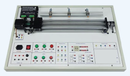
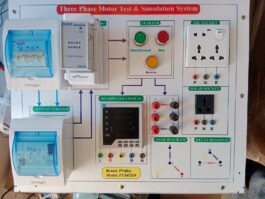
Linear Circuit Lab (1) – Electric Circuits Lab
Description
Brand: PValley
Model: EC-321L1
Country of Origin: China
Features:
- Ideal for electric circuit experiments and design exercises
- Integrated trainer with complete curriculum
- Complete with power supplies and test systems for easyand
- efficient experimentation
- Universal breadboard (1680 tie points) for circuit designand prototyping
- All modules equipped with an 8-bit DIP switch for circuitsfault simulations
Specification:
Body Material:
- Best type Printed Sheet
Sheet Type: Digital
Country of origin: China
Feature:
- Sheet number 26
- Storage Printed temperature 300°c
- Color White/Silver
- Hard Round support board or Acrylic Sheet
Sheet Type: Acrylic
Country of origin: Pakistan
Feature:- Sheet thickness 10mm
- Two-Part Combination(Transparent/white)
- UV Printout
- Safety Breaker.
Brand: Hyundai
Country of origin: South Korea
Feature:- Human Body Sense safety
- Current error detection range is 20mA
- Soft tripping
- Low noise cut off
- Safety tripping
- Low insertion loss and high reliability
- Power supply
Brand: Biologic Tech
Country of origin: TaiwanFeatures:
- SMPS 311VDC/5A
- SMPS 24V/5A
- SMPS 12V/5A
- Panel Box
Brand: Madhav Enterprise
Country of origin: IndianFeatures:
- Shape: Rectangular
- Surface Finish: Smooth
- High quality raw material
- Best structure.Brand: Altech
Country of origin: Bangladesh
Feature:- Sheet thickness 5mm
- Sheet (Silver/white)
- Square Shape
- Power Monitoring
Brand: UNI-T
Country of origin: China
Feature:- Self-operating voltage 12V
- Self-Consumption Current 20mA
- Power Nature
- Two-row for Voltage & Current
- Use Connector
Brand: ZHT
Country of origin: China
Feature:- Female Connector Diameter 2mm
- Male Connector Diameter 2mm
Working area:
- Working area: 45*25 Inch
- Frame size: 50 *30 cm
Technical Specifications:
- Main Unit
- DC Power Supply
- (1) Fixed DC power supply
- Voltage range : ±5V, ±12V
- With output overload protection
- (2) Dual DC power supply
- Voltage range : ±3V ~ ±18V, continuously adjustable
- With output overload protection
- AC Power Supply(1) Voltage range : 9V ~ 0~ 9V
(2) With output overload protection
- Function Generator
(1) Output waveform : sine, square and triangle
(2) Output frequency : 10Hz ~ 100KHz, 4 settings, continuously adjustable
(3) Accuracy : ±5% of full scale value
(4) Output impedance : 50 ohms
(5) Output voltage : ≥ 18Vpp (open loop), ≥ 9Vpp (with 50 ohms load)
- 3 1/2 digit Digital Voltmeter/Ammeter
(1) DC voltage range : 2V, 200V
(2) DC voltage accuracy : ±0.3% of reading + 1-digit
(3) DC current range : 200µA, 2000mA
(4) DC current accuracy : ±0.5% of reading + 1-digit
- Analog Meters
(1) AC current : 0 ~ 100mA ~ 1A
(2) AC voltage : 0 ~ 15V
(3) DC current : 0 ~ 100mA ~ 1A
(4) DC voltage : 0 ~ 20V
- Speaker: 8 ohms, 0.25W speaker with driver circuit
- Variable Resistors
(1) 1K ohms, 0.25W variable resistor with 3 terminals (A, B, C)
(2) 10K ohms, 0.25W variable resistor with 3 terminals (A, B,C)
(3) 100K ohms, 0.25W variable resistor with 3 terminals (A, B,C)
(4) 1M ohms, 0.25W variable resistor with 3 terminals (A, B, C)
- Breadboard:1680 tie-point breadboard on top panel can be easily put into and taken off.
Experiment Modules
- 11 modules, each module is equipped with an 8-bit DIP switch for circuits fault simulations. Students can practice trouble shooting by setting the DIP switch to different positions.
- Detailed solution for fault simulation is included in the instructor’s manual.
- All sockets on the modules accept 2mm plugs.
- Comprehensive experiment manual and instructor’s manual
- Module dimension : (255 x 165 x 30)mm.
List of Modules
- Basic Electricity Experiments Module
- Magnetism Element Introduction Module
- Magnetic Field Module
- Ampere’s Rule Module
- Fleming’s Rule Module
- Electromagnetic Induction
- Electronic Circuit Fundamental Experiments Module
- Basic Electronic Circuit Experiments (1)
- Basic Electronic Circuit Experiments (2)
- Special Electronic Components Experiments Module
- Oscillator Experiments and Applications Module
List of Experiments
- Experiments for Basic Electricity
(1) DC voltage measurement
(2) Using an ohmmeter
(3) Resistor characteristics
(4) DC current measurement
(5) Ohm’s law(6) Power in DC circuit
(7) Series-parallel network and Kirchoff’s law
(8) Superposition, Thevenin’s and Norton’s theorems
(9) Maximum power transfer theorem
(10) DC RC circuit and transient phenomena
(11) AC voltage measurement
(12) AC current measurement
(13) AC RC circuit
(14) AC RL circuit
(15) AC RLC circuit
(16) Power in AC circuit
(17) Transformer characteristics
(18) Series-resonant circuit
(19) Parallel-resonant circuit
(20) LC filter- Experiments for Magnetism
(1) Magnetic devices
(2) Magnetic field
(3) Drawing magnetic curves
(4) Magnetic field strength
(5) Lenz’s and Faraday’s laws
(6) Ampere’s rule
(7) Fleming’s rule
(8) Self Induction
(9) Mutual Induction
(10) Magnetic flux detection- Experiments for Basic Electronic Circuits
(1) Diode characteristics
(2) Rectifier circuit
(3) Filter circuit
(4) Zener diode characteristics(5) LED characteristics
(6) Transistor characteristics
(7) Multimeter functions
(8) FET characteristics
(9) SCR characteristics
(10) UJT characteristics- Experiments for Simple Electronic Circuits
(1) Simple amplifier
(2) Complementary amplifier
(3) Voltage regulator
(4) Push-pull amplifier
(5) Wheatstone bridge
(6) Dimmer circuit
(7) Multistage cascading amplifier
(8) Relay characteristics
(9) Touch-controlled switch- Experiments for Industrial Control Applications
(1) CDS characteristics
(2) Light-controlled circuit
(3) Thermistor characteristics
(4) Temperature-controlled circuit
(5) Sound controlled circuit- Experiments for Oscillator Characteristics and Applications
(1) Blocking oscillator
(2) Electronic birdcall circuit
(3) Astablemultivibrator
(4) LED flasher circuit
(5) LC resonant circuitSoftware:
1. Built-in circuit simulation of experiment modules.
2. Fault simulation is allowed.- Users can flexibly compare the simulation analysis result with hardware signal output.
4. Support virtual instrument.
Accessories
- Experiment Manual and Instructor’s Manual
2. Connection Leads and Plugs
3. Inductors : 0.1H, 0.5H
4. Magnet
5. Key
6. Storage Cabine
Additional Accessories:
- Power Cord: 01 No
- Connecting Wire & Cable
- Complete 5 days Training Included
- User Manual or User Guide
Protection:
Under voltage, Supply and DC Link overvoltage, Phase loss, Drive overload, Instantaneous
Over current, short circuit, Ground fault, etc.

Reviews
There are no reviews yet.