Basic Logic Gate Digital Training System with Logic Software
Description
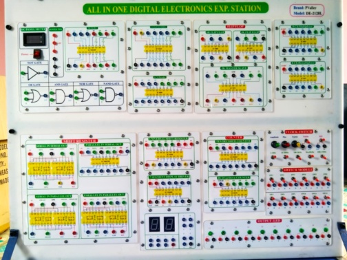
Brand: PValley
Model: DE-2128L
Country of Origin: China
Manufacture: Bangladesh
Description:
The Basic Logic Gate Digital Training System is an educational tool designed for students and professionals to learn and experiment with fundamental digital Combinational logic circuits. It provides hands-on experience with logic gates, Combinational logic circuits and their applications, combined with logic software for simulation and analysis. Using built-in logic gates and simulation software, students can design, test, and analyze basic and advanced digital circuits.
General Specification:
Body Material:
Printed Front Side Sheet
Sheet Type: Digital
Country of origin: China
Feature:
- Sheet number 26
- Storage Printed temperature 300°c
- Color White/Silver
Hard Round support board or Plastic Sheet
Sheet Type: Digital
Country of origin: Pakistan
Feature:
- Sheet thickness 10mm
- Two-Part Combination(Transparent/white)
- UV Printout
Panel Box
Brand: Madhav Enterprise
Country of origin: Indian
Features:
- Shape: Rectangular
- Surface Finish: Smooth
- High quality raw material
Best structure
Brand: Altech
Country of origin: Bangladesh
Feature:
- Sheet thickness 5mm
- Sheet (Silver/white)
- Square Shape
Safety Breaker
Brand: Hyundai
Country of origin: South Korea
Feature:
- Human Body Sense safety
- Current error detection range is 20mA
- Soft tripping
- Low noise cut off
Power Monitoring
Brand: UNI-T
Country of origin: China
Feature:
- Self-operating voltage 12V
- Self-Consumption Current 20mA
- Power Nature
Use Connector
Brand: ZHT
Country of origin: China
Feature:
- Banana Female Connector Diameter 13mm
- Banana Male Connector Diameter 4.5mm
Working area:
- Working area: 34 * 24 inch
Technical Features:
- The Basic Logic Gate Digital Training System should consist of below modules –
- Basic Logic Gates Circuits (Module 1):
- Logic Gate Structure Circuits (DL, RTL, TTL, CMOS)
- Logic Gate Circuits: AND, NAND, NOT, OR, NOR, XOR gates
- Voltage and Current Measurement (TTL, CMOS)
- Interface between Logic Gates Circuits (TTL and CMOS Transform)
- Transmission Delay Measurement (TTL, CMOS)
- Combinational Logic Circuits (Module 2):
- 4 Bits Comparator Circuits
- Tristate and Schmitt Gate Circuits
- Half and Full Adder Circuits
- Half and Full Sub tractor Circuits
- 9 Bits Parity Generator
- Extended Combinational Logic Circuits (Module 3):
- Arithmetic Logic Unit (ALU) Circuit
- Encoder and Decoder Circuits
- Multiplexer and Demultiplexer Circuits
- Digitally Controlled Analog Multiplexer & Demultiplexer Circuits
- Clock Generator Circuits (Module 4):
- Constructing Oscillator Circuit with Basic Logic and Schmitt Gates
- Voltage Controlled Oscillator (VCO) Circuit
- BJT Astable Multivibrator Oscillator Circuit
- Operational Amplifier Oscillator Circuit
- 555 Astable Multivibrator and Monostable Multivibrator Oscillator
- Sequential Logic Circuits (Module 5):
- RS, JK and D Flip-flop Circuits
- Asynchronous & Synchronous Counter Circuit
- Presentably Synchronous Counter Circuit
- Memory Circuits (Module 6):
- Constructing Read Only Memory (ROM) Circuit with Diodes
- Constructing Random Access Memory (RAM) Circuit with D Flip-flop
- Programmable ROM & 64-bits RAM Circuit
- Converter Circuits (Module 7):
- OPA ADC Circuit
- ADC0804 ADC Circuit
- 4-bits R-2R DAC Circuit
- Unipolar and Bipolar DAC 0800 DAC Circuit
- Logic Application Circuits (Module 8):
- Electronics Voting Circuit
- Electronics Wheel-amusement Circuit
- Electronic Competition-answer Circuit
- Traffic Light Circuit
- Function Generator and DC Power Supply Module:
- Waveforms: Sine, Triangle, Square, TTL Pulse
- Amplitude: >10 Vpp
- Impedance: 50Ω ±10%
- Duty Control: 30% ~ 60%
- Display: 6-Digit LED Display
- Frequency Range: 10Hz ~ 100 kHz (4 Ranges), 100Hz ~ 1 MHz (4 Ranges)
- Frequency Control: Reparative Coarse and Fine Tuning
- Constant Voltage Output: ±5V, ±12V
- Variable Voltage Output: 0V ~ ±15V
- Power source: 220 ~ 230V AC, 50Hz, 1 Phase
- Standard accessories with printed operation manual
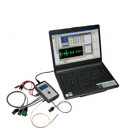
- Should be supplied with below Control System Logic Software:
- Software should combine controller design & implementation into one logical process
- This should reduce learning difficulties and help quickly to understand & create a working control system
- User can use the software icons and wire them together on screen, just as they would draw a control system on a piece of paper
- The icons should include important parts of controllers, signal generators, manually controlled signals & voltages and virtual instruments
- The software can be used to record important variables
- Plotting the results in a chart and exporting data for use in other programs
- Students can create one or more types of controller and simulate the theoretical responses
- The user guide should show users how to use the software and how to build and test common control systems, such as:
- Design and implementation of three-term controllers
- Design of controllers and filters
- Simulated signals: Signal generator (sinusoidal, saw tooth & square wave), with variable frequency, amplitude & offset and D.C. level (fully variable)
- Virtual instruments: Digital meter, Bar graph, Analogue meter, Oscilloscope and Chart recorder
- Controller blocks: Proportional gain, Integral gain, Derivative gain and Phase advance
- Simulation blocks: Integer, First order system, Double integrator, Second order system, First order with integrator system and Second order under damped system
- Other blocks: Gain, Voltage to frequency convertor, Delay, Discrete transfer, Saturation, Summing junction (three input), Multiplier (three input), Switch and Relay
- Fuzzy logic blocks: Fuzzy Pot, Fuzzifier, Defuzzifier, Fuzzy Multiplexer & Demultiplexer, Fuzzy AND, OR & NOT, Fuzzy AND Table, Fuzzy Combined Meter and Fuzzy Single Meter
- Single user licensed version with dongle should be included
Lab Experiment List:
- Understanding Logic Levels (0 and 1) – Testing HIGH and LOW states using LEDs.
- Verification of Truth Tables for Basic Gates – AND, OR, NOT operations using switches and LEDs.
- Verification of NAND Gate as a Universal Gate – Implementing AND, OR, and NOT functions using NAND.
- Verification of NOR Gate as a Universal Gate – Implementing AND, OR, and NOT functions using NOR.
- Implementation of XOR and XNOR Gates – Truth table verification and practical applications.
- Half Adder Circuit using XOR and AND Gates – Binary addition basics.
- Full Adder Circuit using Logic Gates – Implementing multi-bit addition.
- Half Subtractor Circuit using XOR and AND Gates – Binary subtraction basics.
- Full Subtractor Circuit using Logic Gates – Multi-bit subtraction operation.
- 4-to-1 Multiplexer Implementation – Data selection using control lines.
- 1-to-4 Demultiplexer Implementation – Single input distribution to multiple outputs.
- Implementation of 2-to-4 Decoder – Understanding binary to decimal conversion.
- Implementation of 4-to-2 Encoder – Encoding multiple inputs into a smaller binary form.
- SR Flip-Flop using NAND Gates – Truth table verification and state transition analysis.
- D Flip-Flop using Logic Gates – Latching single-bit data and memory storage.
- JK Flip-Flop Implementation – Understanding toggling behavior.
- Design and Simulation of Logic Circuits – Implementing logic gate circuits using software.
- Testing Digital Circuits in Simulation Mode – Verifying outputs before hardware implementation.
Accessories:
- Power Cord: 01 set
- Connecting Wire & Cable
- Complete 5 days Training Included
- User Manual or User Guide
Protection:
Under voltage, Supply over voltage, Drive overload, Ground fault, etc.
Warranty: 1 (One) year with services

Reviews
There are no reviews yet.