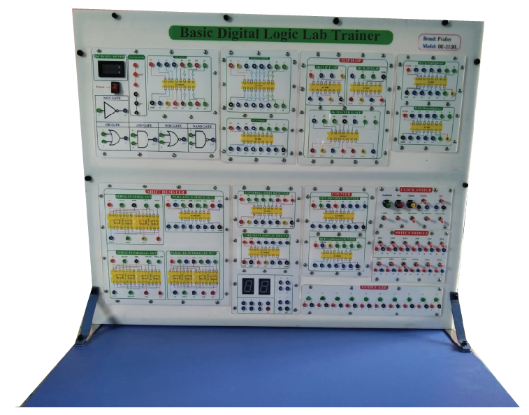
Digital Logic Lab Trainer
Description
Brand: PValley
Model: DE-2128L
Country of Origin: Bangladesh
Features:
- Power Supply,
- Main Unit Dual DC Power Supply,
- Voltage range : +5V/1.5A,-5V/0.3A,+-12V/0.3A,With output overload protection,
- Adjustable DC Power Supply,
- Voltage range : +1.5V ~ +15V,
- current output : 0.5A,With output overload protection,Standard Frequency,
- Frequency : 1MHz,60Hz,1Hz,
- Accuracy : +- 0.01% (1MHz),
- Fan out : 10 TTL load,Clock Signal Generator,
- Frequency : 1Hz ~ 1MHz (6 ranges),1Hz ~ 10Hz,10Hz ~ 100Hz,100Hz ~ 1KHz,1KHz ~ 10KHz,10KHz ~ 100KHz,100KHz ~ 1MHz,
Others Specification:
- Fan out : 10 TTL load,
- Data Switch,-8-bit DIP switch x 2,
- 16-bit TTL level output,
- Toggle switch x 4,each with Debounce circuit,
- Fan out : 10 TTL load,
- Pulser Switch,-2 sets of independent control output,
- Each set with Q,Qftoutput,pulse width > 5ms,
- Each set of switch with Debounce circuit,
- Fan out : 10 TTL load,5 Universal counters,Line Signal Generator,
- Frequency : 50Hz/60Hz,
- Output voltage : 6Vrms,With overload protection,
- Thumbwheel Switch : 2-digit,
- BCD code output and common point input,
- Logic Indicator: 16 sets of independent LED indicates,high /low logic state,
- Input Impedance : ¬ 100K ohms,Digital Displays,
- 2 sets of independent 7-segment LED display,With BCD,
- 7-segment decoder/driver and DP input,
- Input with 8-4-2-1,5mm LED displays,
- InchLoInch and InchHiInch LED display low/high logic state respectively,
- Speaker : 8 ohms,0.25W speaker with driver circuit,
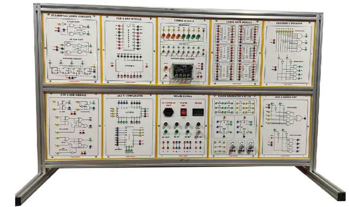
- Experiment Modules,
- All 13 modules are equipped with an 8-bit DIP,switch for fault simulation.,
- Solutions for all fault test are listed in the,experiment manual for userfts reference.,
- 2mm plugs and sockets are used throughout,the main unit and all modules.,
- Comprehensive experiment manual and instructorfts manual.,
- Module dimension: (255 x 165 x 30) mm.,
- Connection plugs are used on the modules to,prevent accidental damages.,
- Individual keeping case for each module,
- List of Experiments,
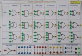
- Basic Logic Gates Experiments,
- Introduction to logic gates and switches,
- Logic gates circuits,
- Threshold voltage measurement,
- Voltage/current measurement,
- Basic logic gate transmission delay measurement,
- Measurement of basic logic gates characteristics,
- Interface between logic gates,
- Combinational Logic Circuits Experiments,
- NOR gate circuits,
- NAND gate circuit,
- XOR gate circuit,
- AND-OR-INVERT (AOI) gate circuit,
- Schmitt gate circuit,
- Open-collector gate circuits,
- Tristate gate circuits,
- Half-adder and full-adder circuits,
- Half-subtractor and full-subtractor circuit,
- Arithmetic Logic Unit (ALU) circuit,
- Bit parity generator circuit,
- Encoder circuit,
- Decoder circuit,
- Multiplexer circuit,
- Demultiplexer circuit,
- Clock Generator Circuit Experiments,
- Constructing oscillator circuit with basic logic gates,
- Constructing oscillator circuit with schmitt gate,
- 555 IC oscillator circuit,
- Monostablemultivibrator circuits,
- Sequential Logic Circuit Experiments,
- Flip-flop circuits,
- J-K flip-flop circuits,
- Asynchronous binary up-counter,
- Asynchronous decade up-counter,
- Asynchronous divide-by-N up-counter,
- Asynchronous binary down-counter,
- Synchronous binary up-counter,
- Synchronous binary up/down counter,
- (6) Constructing dynamic scanning counter with single-chip microprocessor,
- Converter Circuit Experiment,
- Digital/Analog Converter (DAC) circuit,
- Unipolar DAC circuit,
- Bipolar DAC circuit,
- Analog/Digital Converter (ADC) circuit,
- 8-bit converter circuit,
- 3 1/2 digit converter circuit,
- Digital/Analog Converter (DAC) circuit,
- Computer-Based Training,
- Built-in circuit simulation of experiment modules.,
- Fault simulation is allowed.,
- Users can flexibly compare the simulation analysis,Result with hardware signal output.,,
- Accessories,
- Experiment Manual and Instructorfts Manual,
- Connection Leads and Plugs,
- Key,
- Warranty: 01 Year,

Reviews
There are no reviews yet.