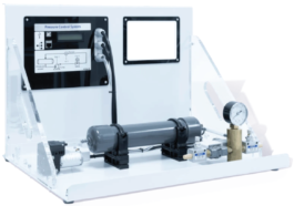
PC based Digital Controller for Process Control Trainer with Control Software
Description
Brand: PValley
Model:PP-874T6
Country of Origin: China
Manufacturer: Bangladesh
Features:
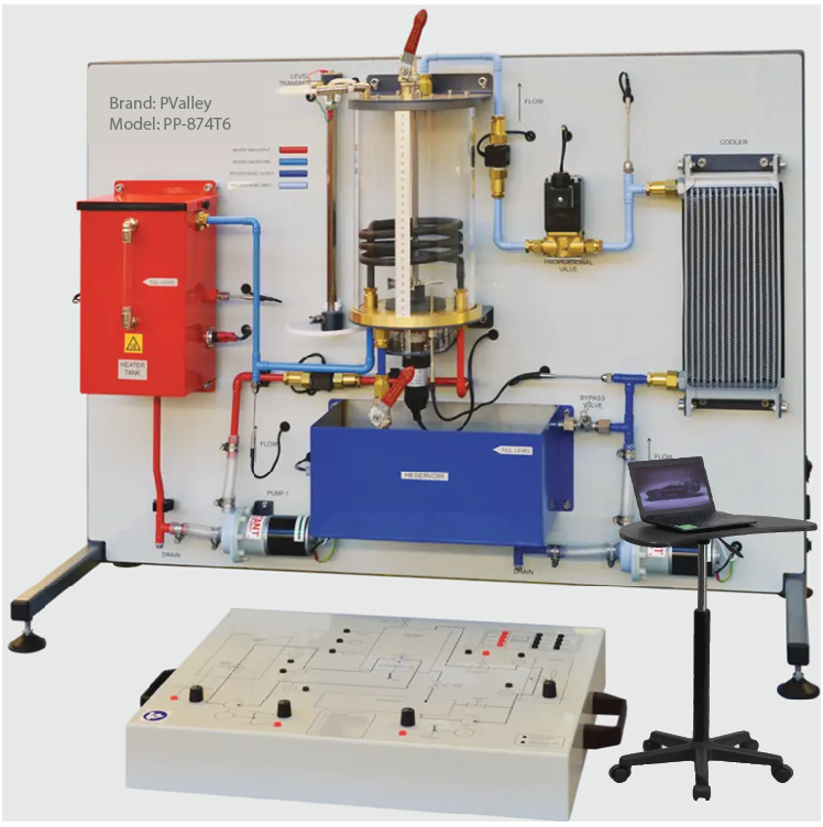
- The PC based digital controller or control module should link to the experiment module of the Process Control Training System to provide access to the connections of each part on the experiment module
- It should include a clear mimic diagram with switches and controls to allow manual control of pump speed, cooler-fan speed, heater power and stirrer of Process Control Training System experiment module
- It also should include sockets and a built-in computer interface (USB)
- This should allow the end user to link each part of the experiment module of the Process Control Training System to a suitable computer for remote control and data acquisition
Process vessel section:
- This section of the Mimic Panel should include sockets for the:
- Input to the Proportional Valve (S) to control its degree of opening – open, closed or some intermediate setting
- Output signal from the Pressure Transmitter (PT), Level Transmitter (LT) and Temperature Transmitter (TT5)
- Output signal from the Flow Transmitter (FT2) measuring the flow rate into the Process Vessel
- Toggle switch labelled ON/OFF to control the stirrer mounted in the base of the Process Vessel of Process Control Training System experiment module
Cooler section:
- This section of the Mimic Panel should include sockets for the:
- Output signal from the Temperature Transmitter (TT3), located at the input to the Cooler
- Output signal from the Temperature Transmitter (TT4), located at the output of the Cooler
- Rotary potentiometer should be included to allow the speed of the cooling fan of Process Control Training System experiment module to be varied from zero to maximum, and hence control the heat transfer rate achieved by the Cooler
Heater tank section:
- This section of the Mimic Panel should include sockets for the:
- Output signal from the Temperature Transmitter (TT1), located in the side of the Heater Tank to provide a measure of the temperature of the water inside the Tank (the outflow temperature)
- Output signal from the Temperature Transmitter (TT2) located in the return pipework to measure of the temperature of the water re-entering the Heater Tank from the Process Vessel (the inflow temperature)
- 2 mm socket and a potentiometer to provide control over the delivery of Pump 1 in the Heater Flow Loop of Process Control Training System experiment module
- Toggle switch to select whether the pump speed is controlled manually (Manual), or whether it is controlled using an external source (External)
Reservoir section:
- This section of the Mimic Panel should include:
- 2 mm socket and a potentiometer to provide control over the delivery of Pump 2 in the Process Flow Loop of Process Control Training System experiment module
- Toggle switch to select whether the pump speed is controlled manually (Manual), or whether it is controlled using an external source (External)
Low water level indicators:
- The bottom right-hand corner of the Control Module should include two LED indicators labelled as Heater Tank Low Level and Reservoir Tank Low Level
ADA section:
- 8 A-D Inputs: 12 bit, ±10V
- 4 D-A Outputs: 12 bit, ±10V
- Should be made in accordance with the latest European Union directives
Technical Specifications:
- Analog Signal Sockets on the Mimic Panel:
- PRT Temperature Transmitters (TT1 – TT5) analogue signal: 0 – 10 VDC output linear
- Conversion details: 10°C per volt, 0V = 0°C, 10V = 100°C
- Flow Transmitters (FT1 & FT2) analogue signal: 0 – 10 VDC output
- Conversion details: 1 L/min per Volt, 0V = No flow
- Level Transmitter (LT) analogue signal: 0 – 10 VDC output non linear
- Conversion details: 0V = Empty vessel, 10V = Maximum level
- Pressure Transmitter (PT) analogue signal: 0 – 10 VDC output
- Conversion details: 100 mbar per Volt, 0V = 0 mbar (gauge)
- Electric Heater analogue signal: 0 – 10 VDC input
- Conversion details: 75W per Volt, 0V = Heater Off, 10V = 750W Maximum Power (Nominal)
- Proportional Valve S analogue signal: 0 – 10 VDC input
- Conversion details: 0V = Closed, 10V = Open
- Pump 1 & 2 analogue signal: 0 – 10 VDC input
- Conversion details: 0V = No Flow, 10V = Maximum Flow
- Dimension (minimum): 75 mm x 490 mm x 360 mm
Control Software Features:
- To be used with control module for real-time control of Process Control Training System experiment module and data acquisition
- Software should combine controller design & implementation into one logical process
- This should reduce learning difficulties and help quickly to understand & create a working control system
- User can use the software icons and wire them together on screen, just as they would draw a control system on a piece of paper
- The icons should include important parts of controllers, signal generators, manually controlled signals & voltages and virtual instruments
- The software can be used to record important variables
- Plotting the results in a chart and exporting data for use in other programs
- Students can create one or more types of controller and simulate the theoretical responses
- The user guide should show users how to use the software and how to build and test common control systems, such as:
- Design and implementation of three-term controllers
- Design of controllers and filters
- Simulated signals: Signal generator (sinusoidal, saw tooth & square wave), with variable frequency, amplitude & offset and D.C. level (fully variable)
- Virtual instruments: Digital meter, Bar graph, Analogue meter, Oscilloscope and Chart recorder
- Controller blocks: Proportional gain, Integral gain, Derivative gain and Phase advance
- Simulation blocks: Integer, First order system, Double integrator, Second order system, First order with integrator system and Second order under damped system
- Other blocks: Gain, Voltage to frequency convertor, Delay, Discrete transfer, Saturation, Summing junction (three input), Multiplier (three input), Switch and Relay
- Fuzzy logic blocks: Fuzzy Pot, Fuzzifier, Defuzzifier, Fuzzy Multiplexer &Demultiplexer, Fuzzy AND, OR & NOT, Fuzzy AND Table, Fuzzy Combined Meter and Fuzzy Single Meter
- Single user licensed version with dongle should be included
Warranty: 1 (One) year with services


Reviews
There are no reviews yet.