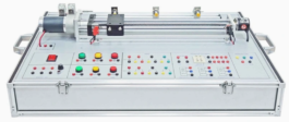
PLC Training System including all Control & Simulation Units
Description
Brand: PValley
Model: PLC-524S9
Country of Origin: China
Manufacturer: Bangladesh
Features:
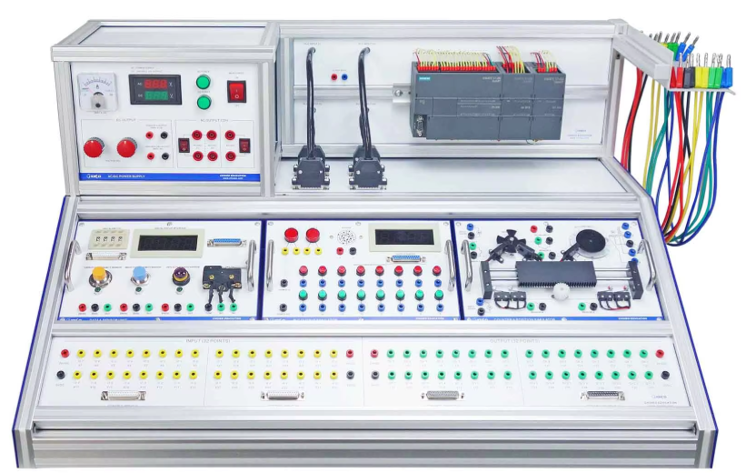
- This should be a tabletop type PLC training system, providing a variety of control & simulation units to form a comprehensive programming training system
- All units should adopt modular design with standard size and carrying handles, user must be able to select modules and build target experiments easily and freely
- A common power case must be attached to the top part together with the PLC unit, both of them should be detachable from the main frame, thus making it convenient for delivery, maintenance and replacement
- To maximize the use of space, the back side of the trainer should be designed with flip-open structure, up to six (or three) modules can be placed inside the frame for storage purpose
- The complete frame structure should be built by standard aluminum profiles, with built-in carrying handle on side part for quick movement of trainer to release the system placement limit
- All terminals should be led out to safety sockets for clear education and easy operation purpose, pluggable cables for experiment connection with sheet steel cable holder be attached on the main frame
Training Content:
- Emergency stop and alarm control
- Slider round-trip of relay-controlled DC motor
- Traffic light signal control
- Sensor and digital display
- Digital switch and digital display
- Motor speed measurement and digital display
- Stepper motor angle control
- Encoding and digital display
- Counting and digital display
- Cylinder control
- PLC input / output data HMI control
Configuration:
- Frame part:
- Complete grooved aluminum profile frame structure
- Two sheet steel with built-in carrying handle on side part
- Rubber cushions on frame bottom
- Flip-open door on back side with two latches for lockup
- Storage chamber available for module up to 6 (or 3)
- Cable holder with 12 slots
- Connectors for main frame with power/PLC units
- AC/DC Power supply unit:
- Input: Single phase AC 220V ±10% with ON/OFF switch and voltage indication
- Fixed 24VDC power output: Max. 6.5A with ampere meter
- Variable DC power output: 0 … 24VDC output, max. 4A. with DVM, coarse/fine ADJ
- AC 220V power output: Two-way with ON/OFF switch
- Indicator: AC/DC power indicators
- Should be attached to aluminum profile frame, easy to be detached
Programmable Logic Controller (PLC) unit:
- With all I/O leading to 25-pin serial connector
- Programming languages STL/LAD/FBD
- Standard Siemens SIMATIC S7-200 SMART relay type
- Digital input/output: 32 inputs, 32 outputs
- Ethernet / RS485 communication with additional serial port
- 85 … 264V AC, 47 … 63Hz
- Should be attached to aluminum profile frame, easy to be detached
- Control system simulation software: Should combine controller design & implementation into one logical process
- This should reduce learning difficulties and help quickly to understand & create a working control system
- User can use the software icons and wire them together on screen, just as they would draw a control system on a piece of paper
- The icons should include important parts of controllers, signal generators, manually controlled signals & voltages and virtual instruments
- The software can be used to record important variables
- Plotting the results in a chart and exporting data for use in other programs
- Students can create one or more types of controller and simulate the theoretical responses
- The user guide should show users how to use the software and how to build and test common control systems, such as:
- Design and implementation of three-term controllers
- Design of controllers and filters
- Simulated signals: Signal generator (sinusoidal, saw tooth & square wave), with variable frequency, amplitude & offset and D.C. level (fully variable)
- Virtual instruments: Digital meter, Bar graph, Analogue meter, Oscilloscope and Chart recorder
- Controller blocks: Proportional gain, Integral gain, Derivative gain and Phase advance
- Simulation blocks: Integer, First order system, Double integrator, Second order system, First order with integrator system and Second order under damped system
- Other blocks: Gain, Voltage to frequency convertor, Delay, Discrete transfer, Saturation, Summing junction (three input), Multiplier (three input), Switch and Relay
- Fuzzy logic blocks: Fuzzy Pot, Fuzzifier, Defuzzifier, Fuzzy Multiplexer &Demultiplexer, Fuzzy AND, OR & NOT, Fuzzy AND Table, Fuzzy Combined Meter and Fuzzy Single Meter
- Licensed dongle must be included
- Input and output panel:
- 32 inputs / 32 outputs 4mm sockets
- 8 common sockets (0/24V)
- 4-25 pin connector
Accessories:
- Cable suite: 4mm, conductor cross section: 16 AWG tinned copper wire, 3kV, 20A, with axial socket
- Manual: Experiments and wiring samples must be provided, together with schematic diagrams
- STEP 7 programming software (copied on CD)
- Portable air compressor:
- Motor: Minimum 1/5 HP, max pressure 6Bar (86Psi)
- Airflow: 30 – 35L/min
- Speed: 1450 RPM or higher
- Tank: 3.0 L or higher
- Auto stop 4Bar (57Psi), auto start 3bar (43Psi)
- Control and Simulation Modules:
- Signal input switch unit (I):
- Latching pushbutton with lamp, 2NO/NC, red
- Momentary pushbutton with lamp, 2NO/NC, green x2
- Contact: 24VDC
- I/O terminal x24
- Stainless steel carrying handles
- Signal input switch unit (II):
- Rotary selective switch, 1NO/NC, black
- Momentary button switch, 1NO/NC, green & red
- Contact: 24VDC
- I/O terminal x12
- Stainless steel carrying handles
- Emergency switch unit:
- Emergency switch, 1NO/NC
- Contact: 24VDC
- Terminal: Yellow x4
- Stainless steel carrying handles
- Buzzer & lamp unit:
- Buzzer, sound-light, 24VDC
- Indicator color: Red, Green x2, Yellow
- Lamp voltage: DC24V
- I/O terminal x10
- Stainless steel carrying handles
- Voltmeters and potentiometers unit:
- Voltage meter: 0 – 15VDC x2
- Potentiometer: 10-turn, R10K x2
- Terminal x10
- Stainless steel carrying handles
- Rotary encoder unit:
- Number of output pulse: 100 pulse per rotation
- Control phase: NPN type AB phase pulse generator, 4 wire
- Input voltage: 24VDC
- Terminal x4
- Stainless steel carrying handles
- Input & output unit:
- Toggle switch x4, Push x7
- Selection switch Output lamp x2, LEDX8
- Buzzer 24VDC
- Terminal x31
- Data & sensor unit:
- Digital switch: 4-digit
- Binary counter (LED display 4 digits)
- Capacitive/Inductive/reflective photo sensor (DC24V)
- Electrical limit switch 1NO/NC
- 25-pin serial port
- Signal control unit:
- Signal system: Traffic signal crosswalk signal
- Road way: Cross-road
- Signal lamp x32
- Terminal x30
- Stainless steel carrying handles
- Relay unit:
- Relay 4 PDT x3
- Input voltage 24VDC
- Contact 24V, 5A
- Terminal x42
- Stainless steel carrying handles Counter & position simulator:
- DC gear motor 24VDC, 200rpm/30rpm
- Stepping motor 4-phase 24VDC
- Photo sensor NPN 24VDC x3
- Limit sensor 3A x4
- Linear bearing gear mechanism Pneumatic unit:
- Solenoid single/double valve
- Single/double acting cylinder
- Sensor 2-wire x3
- Air supply connector
- Stainless steel carrying handles
- Touch panel unit:
- Input power: 220VAC or 24VDC (random)
- Rocker switch with lamp
- Serial 9-pin x2
- Stainless steel carrying handles
- Additional Modules:
- Electric distributor unit:
- Distribution +, – port x12
- Contact for load port x8
- Indicator color: Red/Green LED
- I/O terminal x32
- Supplied with advanced electric simulation system software
- Circuit design: Electric Connection Design, Wiring Property Definition (Color/Thickness), Short Circuit Error Message, Capacity Setting Up, Various Component like Power supply, Motor, LED, Relay, etc.
- Simulation and verification: Operating Status Display, Circuit Error and Electric Flow Check, Colorful Electric Circuit Display, 3D Parts Symbol Library, Time Function Chart, Simulation Error Message
- Virtual component layout and wiring: Ease Circuit Design by Drag & Drop of Symbols, Undo / Redo / Copy / Cut / Paste / Rotation/ Move, 2D / 3D Symbol Conversion, Arbitrary Definition for Component, Virtual Wiring Design
- Electronic Textbook, Electric Theory, Elementary Course and Licensed dongle must be included
- Signal input switch unit (III):
- Button switch, 1NO/NC, Green x8
- Contact: 24VDC
- Terminal x52
- Stainless steel carrying handles
- PLC input controller:
- Toggle switch x8
- Push button switch x11
- Selection switch (SPDT)
- Digital switch: 4-digit
- Terminal x21
- PLC output simulator:
- Output indicator DC24V x16
- Output lamp DC24V x2
- Buzzer 24VDC
- Binary counter (LED display 4 digits)
- 25-pin serial port
- Photo control SCR unit:
- DC controlled AC dimming circuit
- Control input 0…24VDC, power supply 220VAC
- Dimming lamp 15W
- Photosensitive receiving circuit
- D/A converter:
- Input power: 220VAC with indicator
- Toggle switch x9
- DC voltmeter 0…15VDC
- Potentiometer 4.7K
- D/A converter circuit, operational amplifier circuit
- A/D converter:
- Analog input 0 … 15VDC, 8 bits digital output
- LED lamp green x8, red x4
- DC voltmeter 0 … 15VDC
- Potentiometer 4.7K/1K/10K
- Toggle switch x3
- Temperature sensor unit:
- Bridge circuit & output amplification circuit
- Heating & cooling circuit
- DC millivoltmeter 0 … 100mV
- Temperature sensor 3-wire PT100
- Heating unit 24VDC 48W
- Power & terminal transfer unit:
- Rocker switch with lamp
- AC220V input, AC110V output 400mA
- DC -15…+15V output 1000mA
- Terminal conversion 4mm to 2mm x20
- Stainless steel carrying handles
Warranty: 1 (One) year with services


Reviews
There are no reviews yet.